Electronics Symbols And Names

Electronics symbols and names
An electronic symbol is a pictogram used to represent various electrical and electronic devices or functions, such as wires, batteries, resistors, and transistors, in a schematic diagram of an electrical or electronic circuit.
What are the 10 electrical symbols?
10 common electrical symbols found on electrical schematic...
- Phase Meter.
- 240V Outlet.
- Flow Switch.
- NOR Gate.
- Continuously Adjustable Resistor.
- Normally open foot switch.
- Timer off delay, normally open.
- Shielded transformer with magnetic core.
How many electronic symbols are there?
The database includes around 1750 circuit symbols overall. ANSI standard Y32: This standard for electronic component symbols is the American one and is also known as IEEE Std 315.
What is electronic and electrical symbols?
Electrical symbols are a graphical representation of basic electrical and electronic devices or components. These Symbols are used in circuit and electrical diagrams to recognize a component. It is also called a schematic symbol.
What are the 5 electrical signs?
There are five commonly used symbols in Electrical – Switch, Wire, Contactor, Motor, Transformer. These symbols can be used in any electrical drawings. Switches are used for ON/OFF any control circuit.
What are the most common circuit symbols?
Below is an overview of the most used symbols in circuit diagrams.
- Battery. The symbol for a battery is shown below.
- Resistor. The schematic symbol of the resistor are drawn in two different ways. ...
- Potentiometer. ...
- Schematic Symbols of a Transistor. ...
- Schematic Symbol for an Integrated Circuit. ...
- Logic Gates. ...
- Inductor. ...
- Transformer.
What are the symbols in a circuit?
Electrical circuit diagram symbols Electrical symbols are the most commonly used symbols in circuit diagramming. Amplifiers (denoted by triangle shapes) increase the output signal in your circuit. Capacitors (parallel lines) store energy in your system, while resistors (zigzag lines) reduce current flow.
What is the symbol for voltage?
Voltage is measured in volts. The symbol for volts is V. Current is how much electricity is flowing through the circuit.
What are the 5 types of wiring diagram?
6.2: Types of Electrical Diagrams
- Schematic Diagrams.
- Wiring diagrams.
- Block diagrams.
- Pictorial diagrams.
What is a resistor symbol?
The ohm (symbol: Ω) is the SI unit of electrical resistance, named after Georg Simon Ohm. An ohm is equivalent to a volt per ampere.
Why are circuit symbols used?
Circuit symbols are used because they convey in the most elemental manner what a component does, not what it looks like. Components have thousands of variations in packaging; the reader is not interested in what the actual part looks like, but how it works with other circuit elements to form a circuit.
What is K in circuit diagram?
K for relays and contactors. V for tubes and semiconductors. (Consider “V” for “vacuum tube”.) Q for “switching devices for power circuits”, i.e. circuit breakers.
What is a symbol of voltmeter?
The voltmeter is usually represented by the letter V that is placed inside a circle adjoining two terminals.
How do you read electrical symbols?
You see a three-phase ac electric motor symbol. Here this font is the symbol for a solenoid valve.
What is the symbol of bulb?
A light bulb is shown as a circle with a cross inside it.
What is electrical safety symbols?
The common symbol for electricity is a lightning bolt. Electrical Safety Symbols - Voltage or Shock Hazard Symbol. This symbol can be identified by using a bolt or a bolt through a hand, which lets people know that injury or death can occur from nearby high-voltage electrical equipment.
Which is the unit for current?
The ampere, symbol A, is the SI unit of electric current.
What is the symbol for power in electrical?
| Electrical Parameter | Measuring Unit | Symbol |
|---|---|---|
| Charge | Coulomb | Q |
| Inductance | Henry | L or H |
| Power | Watts | W |
| Impedance | Ohm | Z |
What is the symbol of amplifier?
| Invented | Karl D. Swartzel Jr. |
| First production | 1967 |
| Pin configuration | V+: non-inverting inputV−: inverting inputVout: outputVS+: positive power supplyVS−: negative power supply |
| Electronic symbol | |
|---|---|
| Circuit diagram symbol for an op amp. Pins are labeled as listed above. | |
What is the capacitor symbol?
The curved plate represents the cathode (negative) of the capacitor, and the other plate is anode (positive). Sometimes a plus sign is also added to the positive side. The SI unit of capacitance is farad (Symbol: F).
15 Electronics symbols and names Images
Electrical and Electronics Symbols
Electronics on Pinterest Arduino Electrical Engineering and Led

Electronic components and symbols Electronics projects Electronic

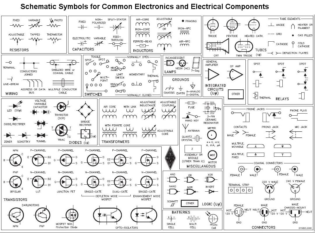
Schematic Symbols for common Electronics and Electrical Components

1000 images about UX and CX on Pinterest

some of the electronics components that are commonly used

Symbols Electronic schematics and Charts on Pinterest

Pin on Inspiration photo

How to Read a Schematic Electronic engineering Electronics circuit

electronics cheat sheet Electrical symbols Electronics basics

Digital Electronics Symbols FlipFlop Linguagem de programao

Electronics Projects Hobby Electronics Electronic Circuit Projects

Standardized Wiring Diagram Schematic Symbols

Pin on Electronics symbols
Post a Comment for "Electronics Symbols And Names"